

An Overview of MECHATROLINK-Ⅲ
MECHATROLINK-Ⅲ achieves high-speed communications at a baud rate of 100 Mbps by applying Ethernet technology to the physical layer. Furthermore, MECHATROLINK-Ⅲ controls 62 SDevices in perfect synchronization using ASICs while achieving the high-speed cyclic communications required for motion control and high-capacity message communications.
∗ A controller, PLC, or similar device connected to the network is referred to as a “Main Device (abbreviation: MDevice)”. A device such as a servo drive, AC drive, or I/O device is referred to as a “Subordinate Device (abbreviation: SDevice)”.
Features
- MECHATROLINK-Ⅲ supports a variety of system configurations through cascade connections or star connections using a hub.
*1: A SDevice device can be easily connected to the MDevice without using a hub.
*2: Devices connected to a hub can be plugged or unplugged without shutting down the system.
The number of nodes that can be connected per unit time is larger than that with a cascade connection.
- Ultra high-speed communications at a baud rate of 100 Mbps and a minimum transmission cycle of 31.25 μs.
- Connects up to 62 SDevice stations.
- Supports large- and small-scale systems with a maximum node-to-node distance of 100 m and a minimum station-to-station distance of 20 cm.
- Allows combining the use of different data sizes (8, 16, 32, 48, and 64 bytes), making it possible to select the optimum size for each device.
- Replace or add SDevices while the machine is running.
- Use the multi-SDevice function to control multiple SDevices with a single communication ASIC.
- A C1 MDevice or C2 MDevice can communicate with SDevices by using message communications.
- SDevices can monitor the cyclic communications data of other SDevices.
Maximum Number of SDevices
The maximum number of SDevices connected to MECHATROLINK-Ⅲ is determined by the transmission cycle time and data size.
| Transmission Cycle Time (μsec) |
Number of SDevices | |||
|---|---|---|---|---|
| 16byte | 32byte | 48byte | 64byte | |
| 31.25 | 1 | 1 | 0 | 0 |
| 62.5 | 2 | 2 | 2 | 2 |
| 125 | 6 | 6 | 5 | 4 |
| 250 | 11 | 11 | 10 | 9 |
| 500 | 19 | 19 | 18 | 17 |
| 1000 | 31 | 31 | 29 | 28 |
| 2000 | 49 | 49 | 47 | 45 |
| 3000 | 62 | 62 | 61 | 59 |
| 4000 | 62 | 62 | 62 | 62 |
| 5000 | 62 | 62 | 62 | 62 |
| 6000 | 62 | 62 | 62 | 62 |
| 7000 | 62 | 62 | 62 | 62 |
| 8000 | 62 | 62 | 62 | 62 |
Notes: 1. The data in the table on the left is for cascade connections with a station-to-station cable length of 1 m.
2. Refer to individual product specifications for specific product information.
Hardware
Communications ASICs
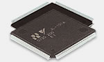
Two-mode MDevice & SDevice:
JL-101 LQFP
20mm□
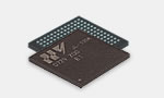
Two-mode MDevice & SDevice:
JL-100 FBGA
SDevice only:
JL-102 FBGA
12mm□
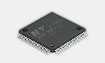
SDevice only:
JL-103 LQFP
14mm□
Commercially available parts are also specified or recommended for other components, and standard circuits are available so that you can design your own devices.
Connector
Two types of connectors are available for MECHATROLINK-Ⅲ.

Industrial Mini Connectors
Assembled models available.

Connector with FA Specification
RJ-45
The user assembles the RJ-45 with Cat5eSTP cable.

MECHATROLINK-Ⅲ Cable
Note:Observe the crossover wiring requiement
described in the MECHATROLINK-Ⅲ Installation Guide.
Software
A number of MECHATROLINK command sets are available for the application layer for different profile types.
The command set for the standard servo profile of MECHATROLINK-Ⅲ has been improved with the addition of new functions. For example, a new positioning command makes it possible to specify the acceleration/deceleration and torque limit at the same time.